
Computer Utility Suite Program Run AnnexToolkit program from your unzipped Annex WI-Fi Basic folder, ensuring it is not blocked by firewall or sandbox etc As the Toolkit evolves over time some things may change but it should remain largely familiar.. The various Tabbed windows are explained below... Serial Port Flasher Serial Upload Tab - the default Flashing screen The first (default) screen is the Serial Upload Tab, used to Flash an ESP device using the Serial Com Port connection. Hover the cursor over any of the controls to pop up a Tooltip description of the control.Read Module Info blue button is non destructive, although it still needs the ESP device to be in flashing mode to read it. Flash Firmware Only green button is non-destructive to any existing data, but will update the existing firmware by overwriting it with the update. Flash Firmware + Data yellow button is fully destructive by overwriting firmware and data, Data Size chooses either Min data or Full distribution. Erase the Flash Memory the Big Red Button erases all flash memory to prepare the device for what would effectively be a new 'virgin' Flash. Tick the 'Advanced Options' checkbox if you wish to display the selected modules parameters in the orange Advanced window. Serial Port is your UART (FTDI) com port - it only shows as available if the port it is actually available. If you are not sure of your devices COM port, check what Toolkit ports are displayed without your device plugged in, then plug the device in and restart the Toolkit, then check to see the what new COM port is now available. Speed is the baud rate setting for your devices UART (FTDI). If confident of your selected device and parameters, try flashing at the fastest speed, then drop to a slower speed if the flashing fails. If not confident of settings, 115200 is a good solid speed that won't take forever. Module Size is the amount of flash memory the device has. Currently only 1Mb to 4Mb is supported (greater than 4Mb can be flashed as 4Mb). The Serial Monitor button on the lower-left opens a special serial monitor that can swap serial port connection with the Flasher utility. File Manager Tab  File Manager Tab The File Manager Tab is your 'mission control' nerve centre used for maintaining control of your remote ESP satellites. Data
displayed by items marked 1, 2, 3 ,5 (not 4) is all dependent on
connection with the ESP device - so no connection means no valid data. 1 Enter the appropriate target ESP IP Address, then click 'Connect to ESP' button, the button will turn green
when successfully connected. Clicking the green connected button will
disconnect, clicking again will reconnect... connection status is also
shown in the window below. it 2 When connected, the ESP firmware version, ESP Ram Free, and ESP Flash Free (SPIFFS) are displayed in the window. 3 When connected, the ESP Date and Time are displayed in the window. The 'Sync Time'
button provides a means of syncing date and time with the computer if
the ESP has no internet access to sync from an NTP server (needs disconnect and reconnect to actually sync time). 4 The 'Local Files' window lists the Local Files and folders in the specified Folder Name that are available for upload. Use the 'List Local Files' button to refresh the folder contents if changed. Multiple items can be selected (using Shift and CTRL keys). Click the 'Upload Files' button to send the selected files through a web-socket wormhole up to the ESP device (assuming it is connected). 5 The 'Remote Files' window list the Remote Files and folders that exist on the connected ESP device. Multiple items can be selected. Click the 'Download Files' button to copy the selected files (including their folder paths) to the specified Folder Name on computer. Caution - clicking the yellow 'Delete Files' button will permanently delete selected files. OTA Tab  OTA Tab The
OTA Tab is your own personal 'Over The Air' update server, allowing
remote ESP devices to have their firmware updated via wifi. Select your required wifi IP address from the dropdown list of available network interfaces, then click the 'Start OTA Server' button. When the OTA Server starts it will open a page in your browser which displays the URLs of the firmware (see below). 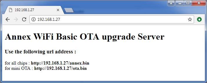 NOTE: the mini OTA is automatically selected by the firmware and is part of a special 2-steps OTA process permitting to update firmware > 512Kbytes. It can evantually selected if the process must be done manually 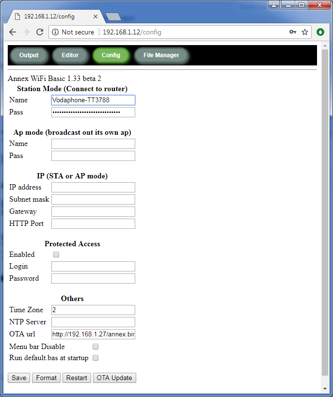 Backup / Restore Tab Backup / Restore Tab You can create a firmware 'binary' backup image, or a data (SPIFFS) 'binary' backup image, or both separately, but not both combined. Note that the appropriate device and com port parameters need to have already been selected in the main Serial Port Flasher tab. Whereas the main Serial Port Flasher tab flashes the firmware pointed to in the Config tab path (currently build/annex.bin), the 'Serial Restore Firmware' button on this page allows flashing of any other specified binary firmware file instead (which need not necessarily be Annex Basic). Config Tab  Config Tab This is where the required paths are specified - paths and filenames may change. UDP Tab  UDP Tab UDP (User Datagram Protocol)
is a 'connectionless' network protocol where UDP nodes broadcast
messages to the network then have no further interest nor any way of
knowing if any other nodes exist or have received any broadcasts... so
it has no handshaking or error-checking capability. (255 is the broadcast address - all network nodes 'listen out' for their own IP address plus the 255 broadcast address) (so if you want to send a UDP message to node 123, you can address it uniquely as 192.168.4.123 or collectively as 192.168.4.255) Only
change the Remote Port number after you know what you are doing, otherwise
you may be causing communications problems for yourself. All
the UDP nodes on a subnet have the potential to speak to each other, but
only if they are using the same port number - if they are all using
different port numbers they will all be isolated from each other... so
the port number can be considered as their membership badge of
recognition. All the demos given here use port 5001 for
consistency, you can change all the ports of your working projects for
something else when done.  The
Message to Send and Message Received areas are fairly self-explanatory,
but if you are wondering about the 3 sliders at the bottom, they were
used for a UDP network demo to control the RGB LED of the Serial Dev Kit
Module shown on the right. HTML Converter Tab The HTML (to Basic) Converter looks simple enough, and is ... but there is actually more to it than meets the eye. Firstly, be aware that the converted output has an extra line added at the top to initialise the variable (usually that's wanted, but not always). Notice
also that nothing is added at the bottom, so nothing will be done with
the converted variable until you make it happen, eg: HTML a$ Obviously the variable can be changed if you prefer (remembering all string variables should end with $ and are not case sensitive). The default separator is the vertical bar "|", which offers the convenience of including double-quotes within the text without causing problems Both the Paste and Copy buttons are smarter than they look - and to get that point across, ask yourself why they are even needed at all ? They have been provided to add convenience... by doing away with the need to 'select all' or delete old contents. Clicking 'Paste' will automatically overwrite previous HTML contents. Clicking the '>>>' convert button will automatically delete all old converted code to make way for the new. Clicking 'Copy' will automatically select and copy all the converted contents to the clipboard. Those are some thoughtful little touches, which will be particularly appreciated when the contents exceed the window size. Syntax HighLight Tab Syntax HighLight Tab |
Join Our DiscussionCOUNTER |
|


